

Description
BBR Digital Expander — 4 Encoders, 4 Sensors and 4 Outputs on One I2C Port
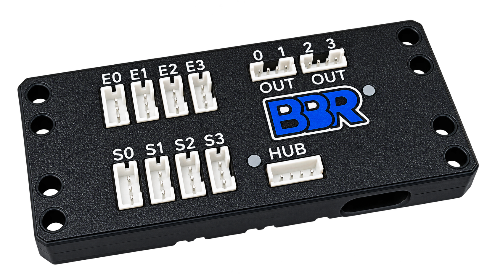
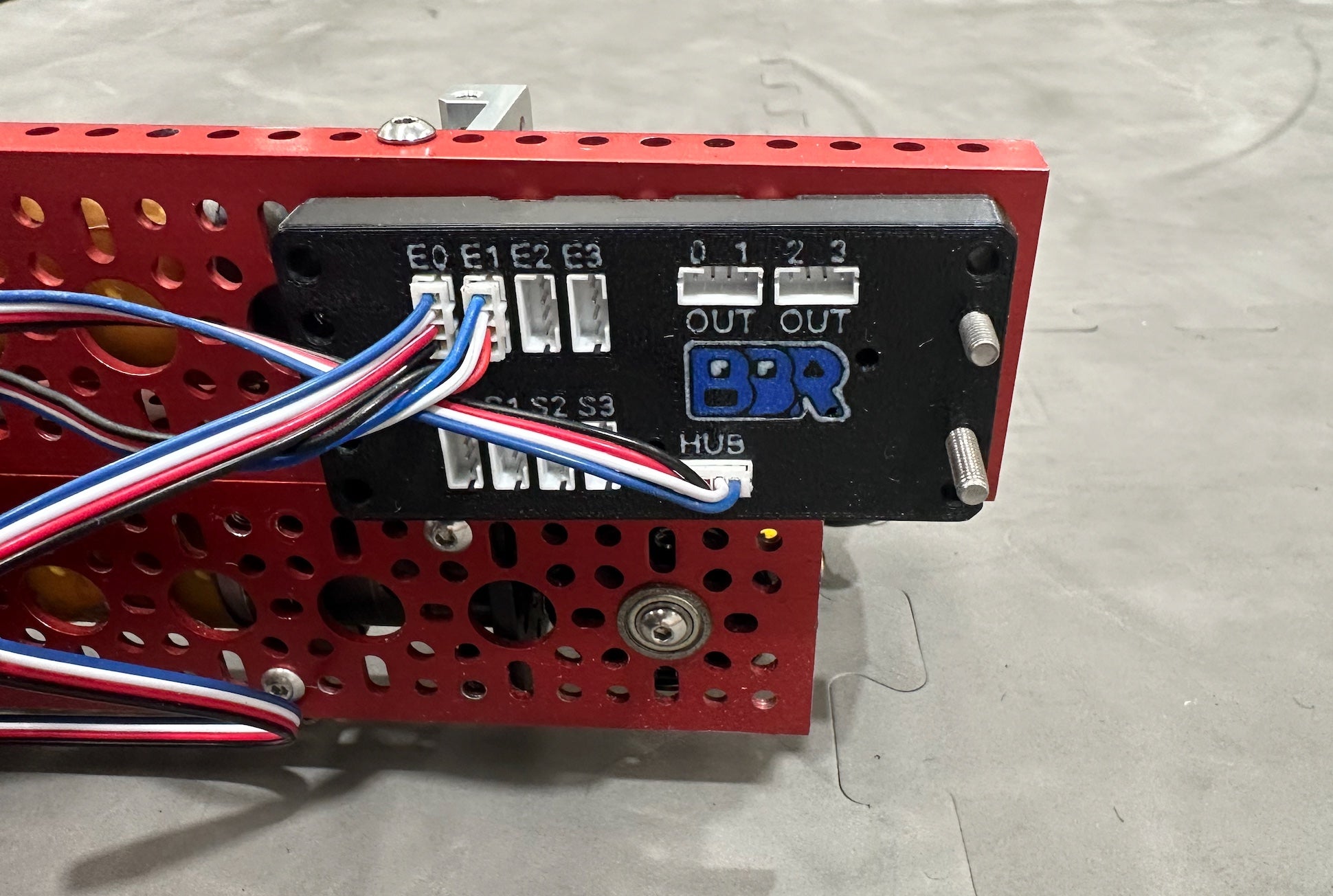
One I2C port in. Four encoder inputs, four sensor ports, four digital outputs and your field position out.
You ran out of ports
Every team hits it. A Control Hub has four motor encoders and a handful of I2C buses, and by the time you have a drivetrain, a lift and an intake, the arm encoder and the colour sensor are fighting over what is left. The Expander hands back four encoder inputs and four sensor ports for the cost of the one port you plug it into.
Your loop got slow
Four I2C sensors read one at a time is four round trips every cycle. The Expander reads all four itself, in parallel, and hands you the answers in a single transaction. Reading four sensors costs about what reading one used to.
Your autonomous doesn't know where it is
An onboard six-axis gyro, fused with two dead-wheel encoders at 1 kHz, gives you field position — x, y and heading all in one read. No maths homework, no second board, no drift correction to write yourself.
It thinks for itself
Teach a sensor port up to seven colours by example and it classifies continuously, faster than your loop can ask. Set a trigger, a colour seen, an object closer than 200 mm, an encoder past a count, the robot facing a heading and the board drives one of its four digital outputs on its own. Your Hub reads that as an ordinary digital input. Everything you teach lives in the board's flash and survives a power cycle.
Works with what you already have
Free, open-source drivers for FTC Java, Arduino C++ and Raspberry Pi Python, MIT licensed, with the same helper names across all three. Underneath it is an ordinary I2C target at 100 or 400 kHz, so anything that speaks I2C can drive it. Firmware updates are drag-and-drop over USB, and everything you taught the board survives them.
Specifications
- Interface: I2C, 100 or 400 kHz. Address 0x38
- Encoder inputs: 4, quadrature or pulse-width absolute, velocity calculated on the board
- Sensor ports: 4, colour (APDS-9151) or distance (VL53L0X), any mix, detected automatically
- Digital outputs: 4, driven by the board, with or without your code in the loop
- Position: six-axis gyro on board, field pose fused at 1 kHz from two dead-wheel pods
- Logic levels: 3.3 V throughout, not 5 V tolerant
- Memory — taught colours, triggers and calibration held in flash through power-off and firmware updates
- Documentation: https://expander.buildingblockrobotics.com